VisionAery Service · Site Survey & System Design
Engineering-LedSite survey & system design — where the analytic actually starts
The best computer-vision model in the world cannot fix a camera pointed at the wrong thing. Site survey and system design is the engineering work that decides whether the analytic gets a fair chance to perform — pole height, downward tilt, pixel density at the leak area, sun angle, surface conditions, IR coverage, and a buildable BOM.
Site design matters as much as the analytic itself
Most failed industrial-AI deployments do not fail because the model is bad. They fail because a camera was mounted at the wrong height, tilted at the wrong angle, framed too wide, pointed at a surface the analytic cannot read, or fighting a lighting condition that no model could overcome. The model gets blamed; the install gets blamed; the vendor gets blamed; nobody fixes it because nobody can agree what "it" is.
Site survey and system design is the engineering work that prevents this — it is where a dependable deployment actually starts. Before a single pole is set, we resolve every camera position against the analytic that camera is intended to serve — pixel density at the leak area, downward tilt against usable range, surface condition against the analytic's supported-surface list, sun angle and IR coverage across the 24-hour cycle. The output is a buildable BOM and a per-camera spec the install crew can execute, plus an honest statement of what this site can and cannot cover.
The reference tables and conditions on this page are pulled directly from the same criteria we hold ourselves to in our POC and pilot agreements. Site design is not a slide deck. It is the constraint set the analytic actually has to live inside.
Survey Methodology
What a VisionAery site survey actually does
Six phases, each resolving a specific failure mode that kills analytics in the field. Every phase produces an artifact that goes into the final design package.
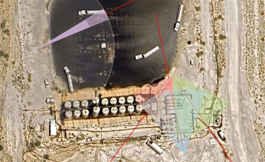
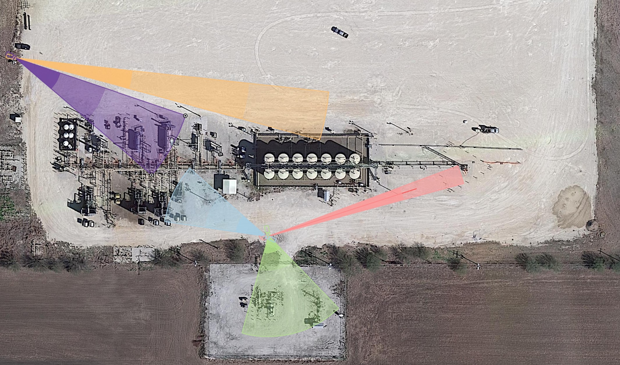
Drone-flown orbit and overhead capture of the pad, tank battery, compressor station, or facility — used to baseline the asset layout, traffic patterns, prevailing-wind orientation, and obstructions before a single camera pole gets specified. The aerial frame becomes the canvas every camera FOV cone is drawn on.
For every analytic in scope (LLD, fire and smoke, flare, perimeter, etc.) we simulate the exact field-of-view cone from candidate mounting positions — pole height, downward tilt, focal length, and lens choice — and overlay the cones against the actual asset geometry. The output is a map: every cone covers what it is supposed to cover, and the gaps are explicit, not discovered after install.
Each candidate camera placement is verified against the analytic's pixel-per-foot requirements. A camera that meets the FOV cone but misses the pixel density at the leak area, the flare tip, or the tank wall doesn't actually serve the analytic — and we'd rather find that on a survey than after a year of running an under-spec scene.
We model sun position over the pad through the day and through the year, identify the hours where direct sun, shadows, or low-angle glare would compromise the analytic, and pair each camera with the right IR illumination strategy for the night case. The goal is a scene that is analytically usable across the entire 24-hour cycle, not just the noon-on-a-clear-day case.
Some surfaces are great for a leak detection analytic; some are not. Some scenes have permanent stains or vegetation in the leak area; some don't. We audit the actual scene conditions a camera will see and either reposition the camera, regrade the leak area, or call out the analytic limitations explicitly so the deployment doesn't pretend to cover a scene it cannot honestly cover.
Every camera position resolves into a power plan, a network plan (PoE, fiber, microwave backhaul, or wireless mesh), and a mounting plan (existing pole, monopole, building structure, skid). The survey output is a buildable BOM and a path from cabinet to camera that the install crew can execute without inventing solutions on the pad.
FOV Reference
Mounting height, downward tilt, and pixel density
Two reference tables we use on every Liquid Leak Detection survey. The first sets usable range as a function of mount height and downward tilt. The second sets pixel density and minimum detectable puddle area as a function of scene width, on a standard 1920×1080 stream. Other analytics use their own equivalents.
 Survey artifact · FOV cones
| Mount Height | Down Tilt | Usable Range |
|---|---|---|
| 15 ft | -5° | 171 ft |
| 15 ft | -10° | 85 ft |
| 20 ft | -5° | 228 ft |
| 20 ft | -10° | 113 ft |
| 30 ft | -5° | 342 ft |
| 30 ft | -10° | 170 ft |
| Scene Width | PPF @ 1080p | Min Puddle |
|---|---|---|
| 15 ft | 128 | 4 sq ft |
| 20 ft | 96 | 6 sq ft |
| 30 ft | 64 | 10 sq ft |
| 40 ft | 48 | 15 sq ft |
| 60 ft | 32 | 25 sq ft |
| Over 60 ft | < 30 | Not supported |
Camera & Stream Baseline
Resolution
≥ 1920 × 1080
Frame Rate
≥ 1 fps
Stream
RTSP · H.264
Camera Type
Fixed or PTZ-parked
Night IR Range
< 50% of datasheet
Scene Conditions
Surface, lighting, obstructions — what we audit before a camera is set
Different surfaces and scene conditions land in different support tiers. The survey audits each scene against the appropriate analytic's supported list and either repositions the camera, recommends a surface change, or calls out the limitation explicitly so the deployment commits to what it can actually deliver.
- Permian caliche
- Light-colored dirt (tan/brown/red/gray) that changes color when wet
- Light-colored gravel that changes color when wet
- Stretched light-color containment (no significant wrinkles)
- Dark dirt or gravel that does not change color when wet
- Light dirt or gravel with minimal vegetation
- Stretched dark-color containment, or non-stretched containment with significant wrinkles
- Cement that is non-polished and non-coated and changes color when wet
- Tile, linoleum, mulch, wood
- Areas of significant vegetation
- Bare, powder-coated, or painted metal
- Polished or coated cement
- Any other glossy or reflective surface
Leak detection area must be largely unobstructed — small pipes are fine; structures that block the expected puddle area are not.
Surface must hold a puddle visible for ≥ 15 seconds before absorption. Highly permeable surfaces require larger test volumes.
Test areas need to be free of stains from prior leaks or significant discoloration that the analytic could mistake for liquid.
Even illumination without harsh shadows, or unlit and lit only by camera IR. Mid-state harsh shadows fight every analytic.
What You Get
Survey deliverables — buildable, not aspirational
Six concrete artifacts that resolve every camera position into a buildable spec and an honest statement of what this site can cover.
Annotated overhead of the asset with every recommended camera position, mounting height, downward tilt, and FOV cone overlaid against the actual scene geometry.
For each camera: scene width, pixel-per-foot at the analytic target, minimum detectable event size, and the analytic(s) the camera is intended to serve.
Per-camera annotation of glare windows, shadow conditions, IR illumination strategy for the night case, and any scenes where artificial-lighting changes are recommended.
Pole, mount, conduit, PoE / fiber / wireless backhaul, edge appliance, and cabinet — itemized to a real BOM the install crew can execute against.
Explicit list of scenes the analytic will and will not cover at this site, with reasoning. The deployment commits to what it can deliver, not what would sound good in a slide.
Sequenced rollout — what gets installed first, what gets validated against the POC criteria, and what gets added in subsequent phases as site-specific training data accumulates.
Frequently asked questions about AI Site Survey & System Design
Related — what the survey enables
VisionAery Analytic · Flagship
The flagship analytic — and the one whose POC criteria most of these reference tables are pulled from.
VisionAery Platform
After the design is built, this is the on-prem control plane that operates the fleet — model push, per-site tuning, OTA, and health.
VisionAery Services
Custom analytics, data integration, hardware sourcing, and remote configuration — the full lifecycle once the survey is approved.
Start with a survey, not a slide
Send us an aerial of the asset, the analytic mix in scope, and the access logistics. We'll come back with a survey plan and a real number, usually within one business day.